Designing a Singlespeed Cog: Getting to know Fusion 360
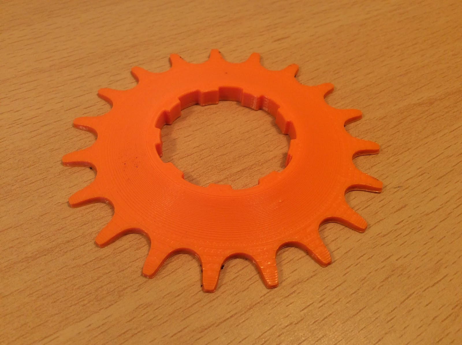 |
| Printed 19T Singlespeed Cog |
Small project modeling single speed bicycle cogs to the ANSI standard. It was a fun project to get more familiar with Fusion 360.
Design:
I didn't have to design a cog from scratch. Its well know that bicycles use an ANSI #40 chain which means 0.5" pitch. Knowing that, I looked in the Machinery's Handbook and found detailed drawings and equations for sprocket design. I really didn't feel like doing all the math by hand so I typed it all into an excel spreadsheet. You can download the spreadsheet here. You can also download the finished stl files from from my account on Thingiverse.com. (https://www.thingiverse.com/thing:2511621) |
| Dimensioned image of an ANSI sprocket Tooth Form. Also includes basic measurements for standard sizes. I converted the measurements to mm for quick reference. |
 |
| Equations to calculate values shown in the dimensioned image above. |
 |
| Screenshot of Sprocket Calculator in Excel. Auto-calculates all values based on Pitch and Number of teeth. Red values are ones used in Fusion 360. Download Link. |
Modeling in Fusion 360:
 |
| Design Process in Fusion 360 |
 |
| Sketch of sprocket tooth. Dimensions are for a 19T cog. |
3D Printed Final Design:


Comments
Post a Comment
Write a comment here. Let me know what you think...